As part of the Research and Development team at Avidbots, I brought an autonomous floor scrubbing robot from conceptual design to production and sales in the short span of two years.
I was primarily responsible for the creation of the Manual Drive Interface, which is how users are able to manually move the unit when required. It was important that it was intuitive, ergonomic, and remained within the tight constraints of the robot footprint.
The system is comprised of a welded sheet metal structure, control electronics, and plastic shells. Due to the tight timeline of the development phase of this project, the shells were initially vacuum cast for fast, soft tooled initial production. Then, the shell design was modified for injection molding so that hard tool production could be implemented for cost savings. All designs included multiple rounds of vendor collaboration in order to ensure the most production efficent designs were released.
As part of my role as Mechatronics System Designer at Sheertex, I worked to increase the efficiency of industrial machinery through automation and process improvements.
In order to increase the throughput and decrease the cost of a packaging operation, a solution to eliminate the manual label application on an existing packaging machine was required. Due to the constraints of the production environment and increasing demand for product output, the timeline for design and experimentation was very tight, requiring ingenuity and re-use of parts in the factory.
The mechanism was designed using the linkage graphical method, then modeled in Fusion 360. It consists of three pneumatic cylinders - two of which rotate and depress the sticker applicator and one which folds the edge of the sticker 90 degrees to apply it to the top face of the box. Each cylinder is controlled by the machine PLC.
The labels are printed with a Novexx thermal label printer, which interfaces with both the OMRON PLC and the internal product tracking software to print the correct label at the correct time in the cycle.
This solution eliminates 5 seconds of manual work time, freeing an operator to work between two packaging machines to place product into transport bins, as opposed to one operator per machine manually applying labels and placing into bins.
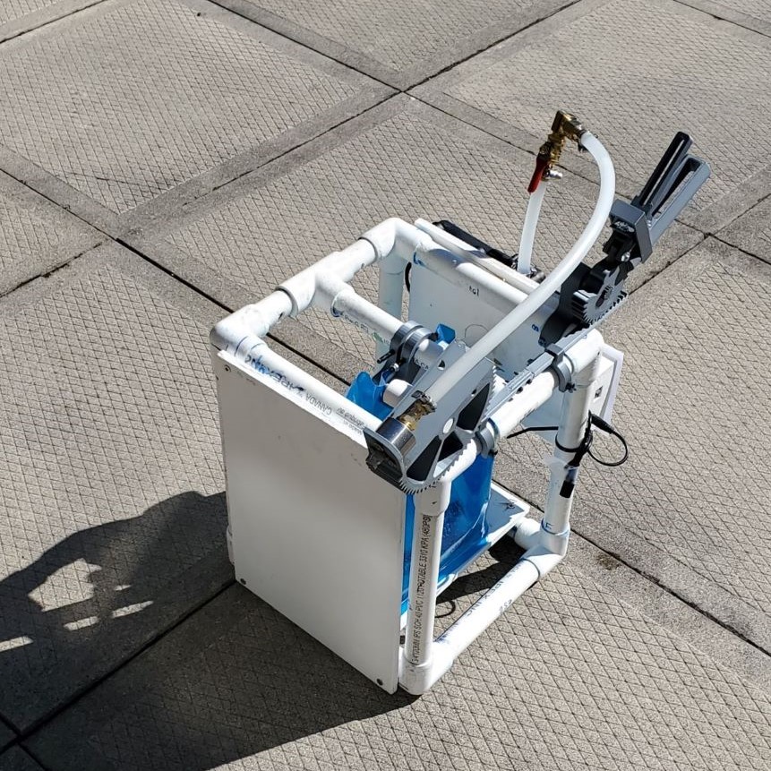
During my final year in University, I worked in concert with two others on our year-long capstone project to design and prototype a inexpensive alternative to current fire extinguishing solutions.
Financially disadvantaged, rural, and cottage communities are more at risk when it comes to fires due to a lack of resources for community firefighters and lack of fire-preventative measures. An inexpensive, easily operable, portable device that can safely extinguish small fires and suppress larger ones while reducing overall human interaction with the fire was designed to remedy the issues of fire damage and injuries in the target demographic.
Working to our strengths within the team, I led the design side of the project by creating and maintaining a design dependencies and revisions Gantt chart, which synchronized the design work between the three team members. I also designed the aiming mechanism, tank support, and overall structure. In order to prove the fidelity of the design, I fabricated and designed testing procedures for a PVC prototype.
As part of the project, I created and kept the hourly and financial budgets up-to-date, and was responsible for specifying and purchasing required components. With my team mates, I also presented our work in multiple presentations and design reports.
Due to the weight of woks used to toss fried rice in restaurants, chefs are commonly subjected to musculoskeletal discomfort. In a group project for my ME 547 Robot Manipulators: Kinematics, Dynamics, Control class, we simulated the the tossing motion using a robotic manipulator such that the accuracy of the motion was maintained. Using a kinematic model for the wok during the tossing motion, waypoints for the motion were generated and inverse kinematics were then applied to find the joint vectors needed for the motion. This motion was then implemented in the simulation and validated by comparing the waypoints to those in a peer reviewed research study and data from motion capture of chefs performing the motion.
I was primarily responsible for creating the transformation matrices required to create the waypoint motion, creating a CAD model of the wok, and assisting with the joint vector calculations.
A major advantage of composite materials - especially fibre reinforced composites, is the ability to combine material properties of the constituents. The addition of fibres with good mechanical properties, such as high strength, but which are brittle on their own may be combined with more ductile matrix materials in order to produce a material that can perform better than either individual component.
The fatigue performance of engineering materials is also an important quality to consider when fabricating composites as real-life applications often are not limited to static loading. For example, in the aerospace industry, there are many parts that must withstand cyclic loading, due to cycles of pressurization and depressurization, vibrations, or rotation during service. Therefore, to use textile-reinforced composites in real-world applications, it is important to have an understanding of the microscopic damage development caused by cyclical loading.
For my ME 533 Non-metallic and Composite Materials, I designed and prototyped test mechanisms which could be used to test the bending, tensile, and fatigue properties of composites. Lab access was limited due to the COVID-19 pandemic, therefore these mechanisms were designed to be easily replicable at home with minimal tools and materials.
The prototypes were validated using fibre reinforced composites made from yarn and hot glue. The bending and tensile test machines fulfilled the requirements of the project, however the fatigue mechanism required more redesign which was not feasible during the scope of the class project. This remains a project which I would like to come back to and devote more attention to in order to successfully complete the fatigue tester.
As part of my ME 380 Mechanical Engineering Design Workshop course I worked with five other students to iteratively design a six degree of freedom platform used to move a marble through a maze.
We created an initial platform that was used as the benchmark for the improvements in phase two. It utilized servo motors attached to rods to move the platform, which led to jerky and unreliable movements. Another problem was that a manual reset was required to move the marble back to the start of the maze which was a safety risk to the user.
The phase two product was designed to solve these problems by changing two aspects of the platform; the rods were replaced with a hydraulics system and an automatic marble reset system was developed. I was primarily responsible for the design of the ball reset system, which used a spring load to separate the base of the maze from the walls and allowed the marble to be automatically tilted back to the start position. I also assisted with the design of the hydraulics, which used syringes and tubing to move the platform.
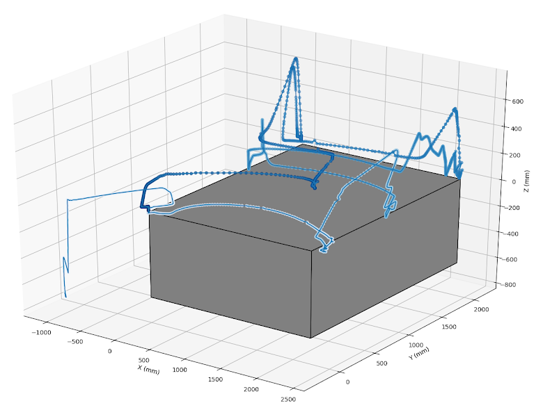
I designed and fabricated a system of instrumentation to report the position of a tool attached to the arm of a Bobcat Excavator. In order to do so, I researched and selected rotary encoders which were then mounted to the arm along with all other required components, and drove the excavator to gather test data.
Electrical components were selected and assembled into 3-D printed storage containers, including battery packs and Particle Photon micro-controllers, and mounted using magnets. The mechanical components required to translate the motion of the arm into encoder-readable data were also 3-D printed, then attached using adhesives and magnets. All 3-D printed parts were designed using AutoCAD Inventor.
Additionally, I wrote programs in C++ to translate, transmit, and read the data from the encoders. I also wrote others in Python using MatPlotLib to calculate the position from the angular data, remove digital noise, and plot the position of the tip of the tool over time.
I am a design/build mentor and the main CAD mentor for the Rockway Robotics FRC team. Rockway is a team of 25 high school students who participate in the FIRST Robotics Competition, where every year they must design and build a new robot to play a specific "game".
Watch this year's robot in action here (on the bottom left, with blue bumpers!)
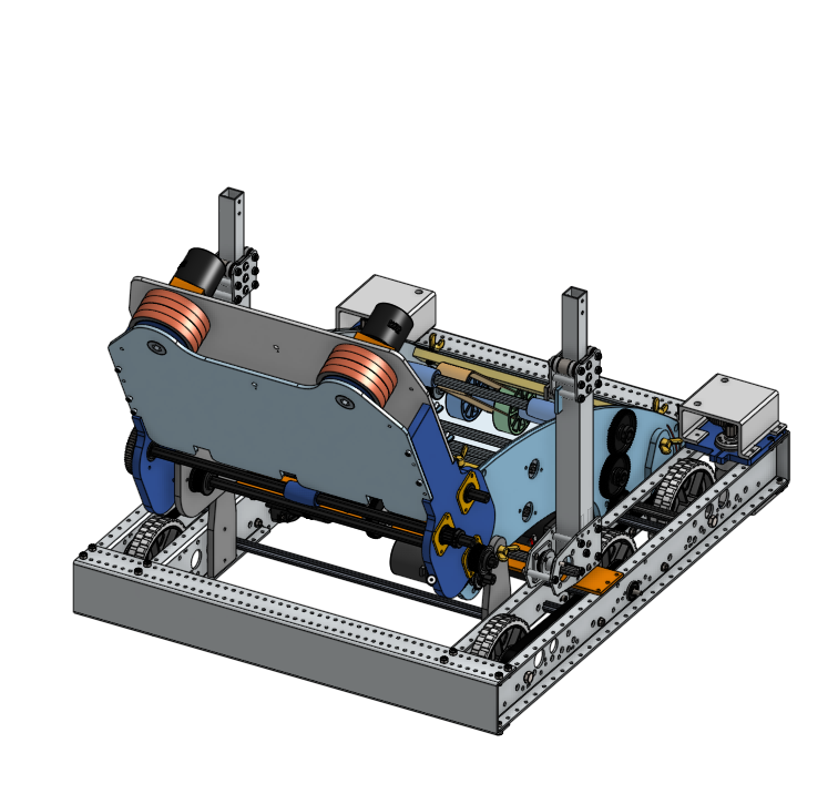
Over the last year, I have brought the team from having a basic, incomplete model of their robot to a fully detailed model that was used for outsourcing fabrication, by breaking down the skills required for proper CAD into small, interesting sections for students. I acted as the model manager, ensuring that the students maintained a high standard of CAD while still allowing them to make mistakes as they learned to use OnShape.
As I continue to work with the team, my goal is for a student to gain familiarity with Onshape such that they can manage the model themselves, allowing me to transition into a teaching and support role.